Need help or have questions?
Join our community of builders on Discord to share your progress, ask for troubleshooting, or just chat about the project!
💬 Join the OpenGate Discord🚧 Work in progress
The gate model itself is 100% finished. The ramp — the part the gate and motor mount onto — is still being improved:
Expect updates to the ramp file as the design gets validated. The assembly steps below already reflect the current models.
3D Printed Parts
Download the 3D models for the motorized SG-1 gate:
Hardware & Sounds
Electronic parts that can't be assembled on the official PCB — if you want to order them:
- 1) NEMA17 stepper motor — recommended models: 17HS4023, 17HS4401, 17HS3401, or 17HS15-1504S. 1.3–1.5A is enough, and the motor's depth doesn't really matter (tried both 17HS4023 and 17HS15-1504S on my prototype). I used this one (17HS15-1504S) on my own gate.
⚠️ Two important things:- The cable has to be a JST-XH 6-pin to Dupont 4-pin cable, like this one.
- NEMA17 motors aren't all wired the same way — usually it's "ABAB" for the pins, but sometimes it's "AABB". The PCB has both options, so you can try either — just never plug both at the same time.
- 2) DRV8825 stepper driver — example.
- 3) DFPlayer Mini (+ any microSD card formatted FAT32) — example.
- 4) 3W 8Ω speaker — example.
- 5) LM2596 buck converter (adjustable) — example. Untested with the LM2596S variant (the one with a 7-segment display), but it should work just as well.
Hardware to plan for:
- M3 inserts (2 to 4mm) ×2
- M3 screws (10 to 12mm) ×4 — M3×10mm is the ideal length, but M3×12mm also works
- Two COB LED strips, 5mm, 5V, 100 LEDs/m (the exact LED count on the strip doesn't matter much for this gate)
Understanding the Parts
- The ramp: both the gate and the NEMA17 motor mount onto this piece, using M3 inserts (glued in, or melted into the plastic with a soldering iron) and M3 screws.
- The ring core: the gate's main body. This is where the glyph and chevron LED strips are routed, and where the rotating glyph ring sits.
- The rotating glyph ring: sits directly inside the ring core. It's held in place by the 9 tabs near the chevrons at the back, by the NEMA17, and by the front ring of the gate.
- The front ring: clips onto the ring core to close up the gate. Glue the 9 chevrons — printed in transparent red — onto it.
- The inner ring / event horizon: the last piece to go on. It can be secured with glue or with poster putty (Patafix).
Printing tips: use at least 80% infill for the motor gear and the rotating glyph ring. No supports are needed for any part except the rotating glyph ring.
Practical tips: sand the back of the rotating glyph ring to prevent friction during rotation. The gate is very easy to take apart — if something feels off, don't hesitate to backtrack a step.
Mount the Motor & Ring Core
Place the NEMA17 onto the ramp and screw it in using the two lower screws.
Then screw the ring core onto the ramp using the two lateral M3 screws, plus the two lower central screws — these also secure the top of the NEMA17.
Note: a few extra, more lateral holes are already there for possible future ramp designs.
Chevron LED Strip
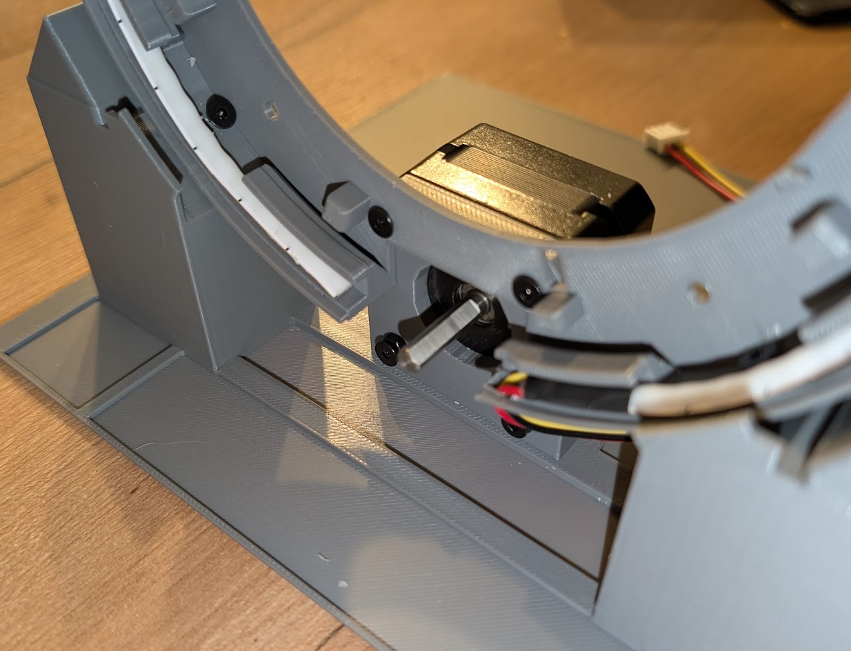
Once the gate is firmly mounted, run the 5mm 5V COB LED strip for the chevrons around the outside of the gate.
A small hole near the lower right of the motor lets the cable pass through.
Motor Gear & Spacer
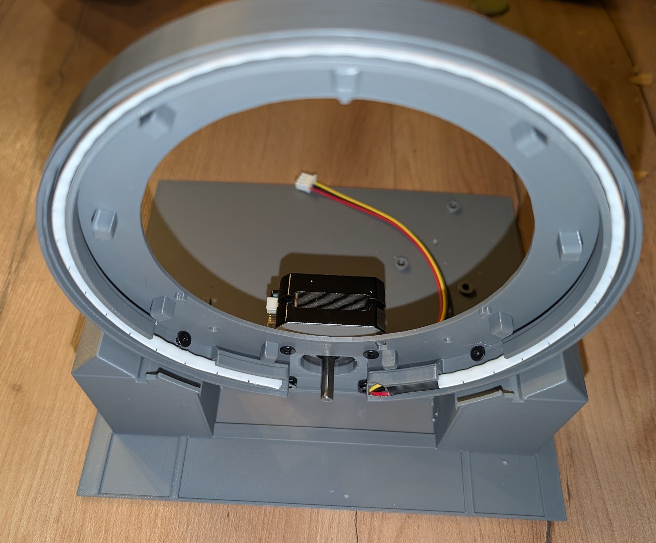
Place the NEMA17 gear and its spacer directly onto the motor shaft.
The spacer is optional, but it helps keep the gear from sliding back over time — it should be 10 to 12mm (adjust the size as needed). What matters most is that, once assembled, the rotating glyph ring and the gear stay well aligned and parallel.
Event Horizon LED Strip
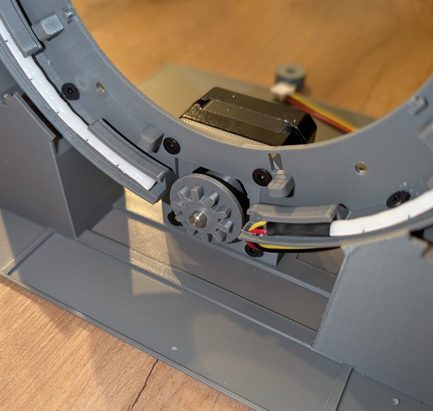
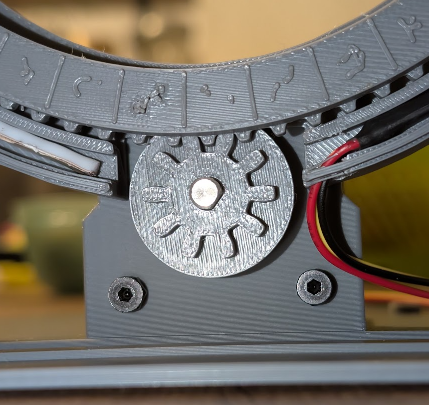
Run the event horizon LED strip between the notch that holds the inner ring and the tabs that hold the rotating glyph ring.
A few dots of glue are recommended to keep the strip from rubbing against the rotating ring.
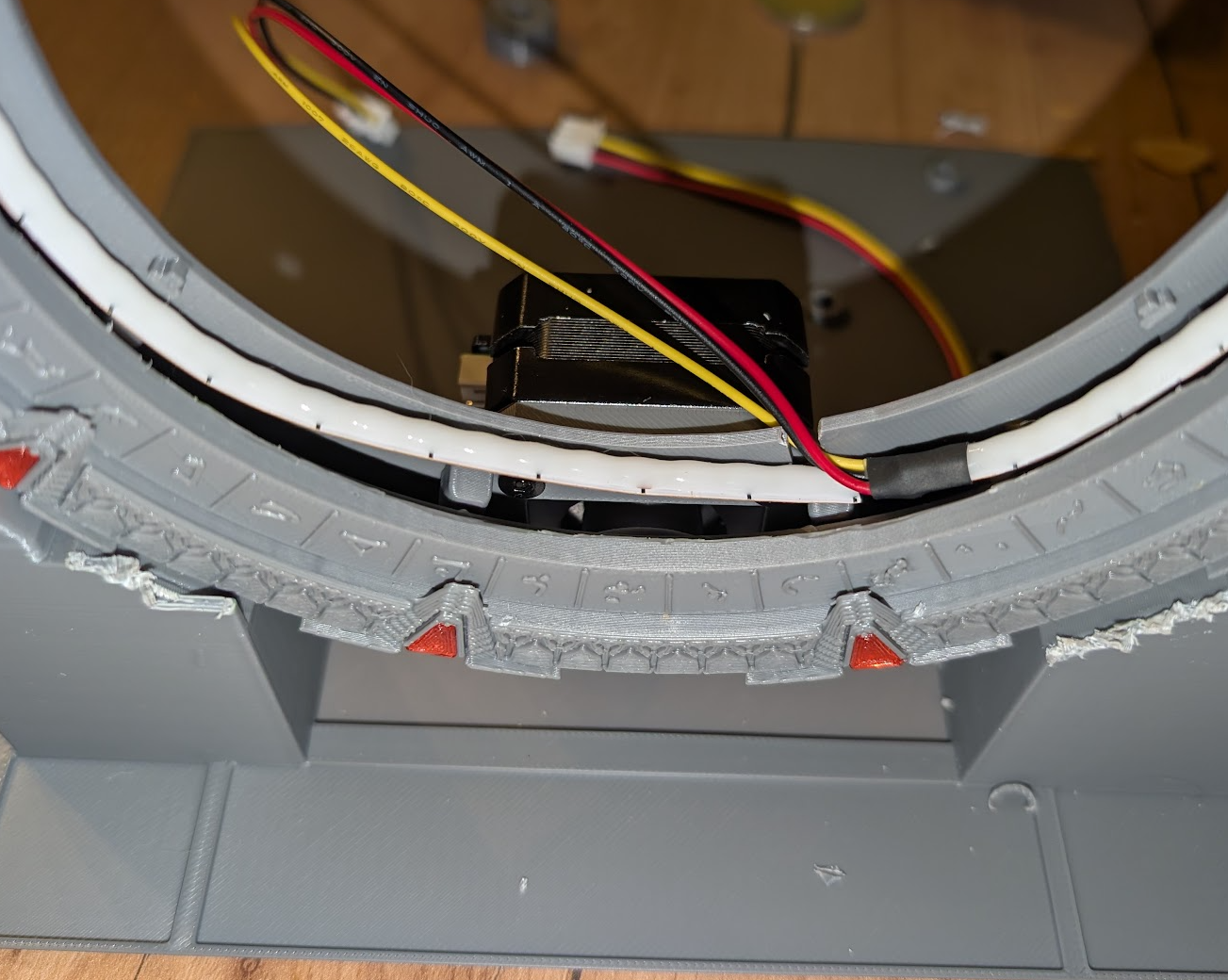
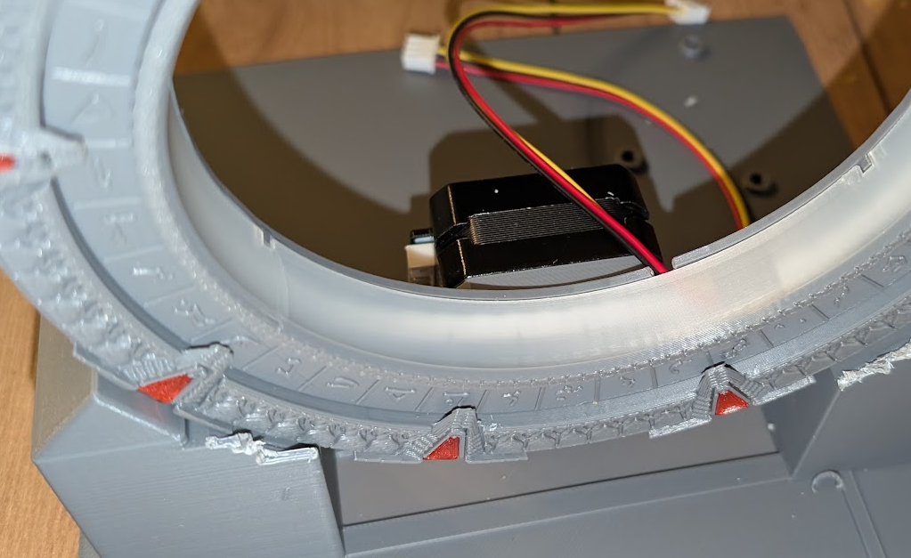
Inner Ring
Place the inner ring — this is the final piece of the mechanical assembly.
The rest of this tutorial — wiring and preparing the electronics — is coming soon!